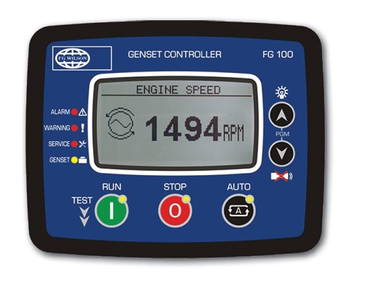
FG 100
Presentation
The FG100 panel range, which is the standard / default panel for the 13.5 – 220 kVA range, allows you to easily monitor and control the generator, providing important diagnostic information, while ensuring that the unit operates in safe parameters.The FG100 digital control panels offer simple and intuitive menu navigation and control of your generator set operations. Key information is displayed via the LCD screen and LEDs using universally recognized symbols, eliminating the need for complex instructions or language settings.
Benefits
- Automatic start control mode
- Integrated measurement and controls
- Monitoring, protection, condition, faults and measurement displayed via LCD and LEDs
- Robust electronic package
- Symbols for simple, intuitive control
CHARACTERISTICS
- Configure parameters via the buttons on the front panel or via the USB interface
- 128 × 64 LCD graphic display
- Configurable inputs / outputs
- Motor monitoring and current parameters
- Run / Auto / Stop keys with LED indicators
- Under / over voltage protection

| FG100 | DSE4520 | DSE7320 | DSE7410 | DSE7420 | PW1.1 | PW 1.1+ | PW 2.1 | PW2.1+ | MRS16 | IG200 | EG2500 | |
| Control Function | Auto Start | Auto Mains Failure | Auto Mains Failure | Auto Start | Auto Mains Failure | Auto Start | Auto Start | Auto Start | Auto Start | Auto Start | Sync | Sync |
| I/O | ||||||||||||
| Digital Inputs | 6 | 4 | 8 | 8 | 8 | 4 | 6 | 6 | 6 | 7 | 8 | 10 |
| Dedicated E’stop Input | x | x | ✓ | ✓ | ✓ | ✓ | ✓ | ✓ | ✓ | x | ✓ | x |
| Digital Outputs | 5 | 4* | 6 | 6 | 6 | 6 | 6 | 8 | 8 | 6 | 8 | 11 |
| Dedicated Fuel And Crank O/Ps | x | ✓ | ✓ | ✓ | ✓ | x | x | x | x | x | x | x |
| Analog Input | 3 | 3 | 6 | 6 | 6 | 2 | 3 | 3 | 3 | 4 | 4 | 4 |
| Mpu Input | x | x | ✓ | ✓ | ✓ | ✓ | ✓ | ✓ | ✓ | ✓** | ✓ | ✓ |
| Rs232 | x | x | ✓ | ✓ | ✓ | x | x | x | x | Option | Option | x |
| Rs485 Modbus | Option | x | ✓ | ✓ | ✓ | x | x | ✓ | ✓ | Option | ✓ | ✓ |
| Can Bus Engine | ✓ | ✓ | ✓ | ✓ | ✓ | ✓ | ✓ | ✓ | ✓ | ✓ | ✓ | ✓ |
| 2Nd Can Bus | x | x | x | ✓ | ✓ | x | x | ✓ | ✓ | x | ✓ | ✓ |
| USB | ✓ | ✓ | ✓ | ✓ | ✓ | x | x | x | x | ✓ | ✓ | x |
| Ethernet | x | x | x | ✓ | ✓ | x | x | x | x | Option | x | x |
| SNMP | x | x | x | ✓ | ✓ | x | x | x | x | ✓ | ✓ | x |
| Power Measurement | ||||||||||||
| kW | ✓ | ✓ | ✓ | ✓ | ✓ | x | x | ✓ | ✓ | ✓ | ✓ | ✓ |
| kVA | ✓ | ✓ | ✓ | ✓ | ✓ | x | x | ✓ | ✓ | ✓ | ✓ | ✓ |
| kVAr | ✓ | ✓ | ✓ | ✓ | ✓ | x | x | ✓ | ✓ | ✓ | ✓ | ✓ |
| pf | ✓ | ✓ | ✓ | ✓ | ✓ | x | x | ✓ | ✓ | ✓ | ✓ | ✓ |
| kWh | x | ✓ | ✓ | ✓ | ✓ | x | x | ✓ | ✓ | ✓ | ✓ | ✓ |
| kVAh | x | ✓ | ✓ | ✓ | ✓ | x | x | ✓ | ✓ | ✓ | ✓ | ✓ |
| kVArh | x | ✓ | ✓ | ✓ | ✓ | x | x | ✓ | ✓ | ✓ | ✓ | ✓ |
| Event Recording And Plc Function | ||||||||||||
| Real Time Clock | ✓ | ✓ | ✓ | ✓ | ✓ | x | x | ✓ | ✓ | ✓ | ✓ | ✓ |
| Event Log | 400 | 50 | 250 | 250 | 250 | 40*** | 40*** | 40*** | 40*** | 350 | 350 | 300 |
| Plc Capability | x | x | ✓ | ✓ | ✓ | x | x | x | ✓ | ✓ | ✓ | ✓ |
* 2 are used if in Auto Mains Failure configuration
** Consumes 1 Analogue input
*** Has 40 event slots each of which can record up to 40 instances of an event


